Wednesday, October 21, 2009

How to Install a fuel pressure gauge


0 ความคิดเห็น


This writeup will show you how to install an Autometer 2 1/16" fuel pressure gauge in your engine bay.


Materials Used:
Autometer Fuel Pressure gauge
Part # 3312
Autometer Gauge Mount bracket
Part # 2236
XRP 1' braided hose with 90° end
Part # 649012
2 XRP Hose Ends
Part # 230004
XRP Threaded 'T' Fitting
Part # 982404
2 hose clamps
(can be bought at any parts store)


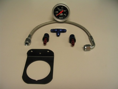
Below are some pictures of the parts, and installation instructions:
1
These are all the parts needed.


Step 1:
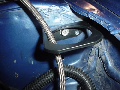
Find a place to mount the bracket where you will have enough for the braided line to reach. For this, I used the driver side strut tower, and used one of the existing holes to screw down the bracket.
2
Step 2:
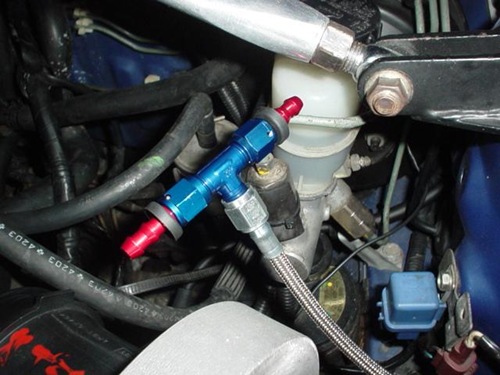
Put all the fittings together. The 2 hose ends go on the ends of the 'T' fitting, and the line will go on the bottom.
3
Step 3:
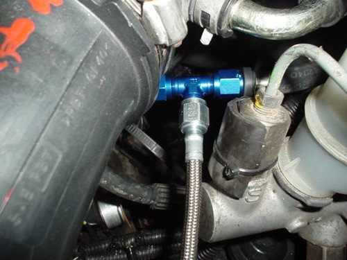
Find the proper fuel line to splice into. This will be the line coming off the fuel filter, going to the feed on the rail (also seen in the picture above). Once you find this line, cut it in a spot where you can put each piece of hose on the XRP fittings.
4
Step 4:
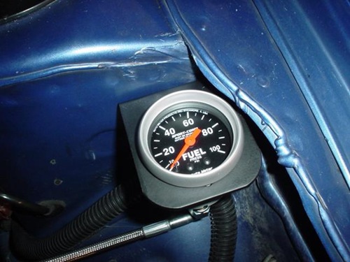
Connect the 90° end of the line to the gauge and mount the gauge in the bracket (make sure you run the line through the bottom of the bracket, so the gauge can drop right in after the line is tightened).
5
Step 5:
Turn the ignition on, and check for leaks, if you see a leak, tighten the fittings better.


Step 6: Optional
If you want to go that extra mile, and have a lighted gauge, connect the light bulb. Just ground (black wire) it somewhere near where its mounted, you should have other bolt holes, or grounds in that area. For power (white wire), you will need to extend the wire to reach the driver side sidemarker. This will make the gauge come on when you turn your parking lights on. Splice the white wire into the positive sidemarker wire, and you're done.


There are other alternatives to this, but this is just one that I have done.

Serban

How to Disassemble B13 transmission


0 ความคิดเห็น


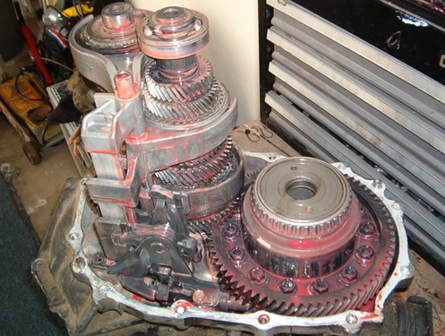
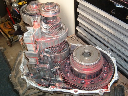
I dont know if anyone has ever bothered with disassembling a B13 transmission. I know Coalition did a B15 trans, and its somewhat similar. I was "donated" a cracked transmission from fellow forum member Gee805 from when he cracked his trans at the line at the local dragstrip I had a spare tranny at my parents house with a blown LSD. So I took apart his transmission to steal his LSD and swap it into my otherwise good transmission. Disassembly is rather easy and should not take more than an hour to complete.


Tools needed:
10mm socket
12mm socket
snap ring pliers
a few flat head screwdrivers


First and foremost, we have the specimen..
1
Remove the top cover using a 10mm socket
2
Once the cover is removed, you will notice a snap ring that needs to be removed
3
4 
We can now proceed to remove the 12mm bolts surrounding the bellhousing
5
The bellhousing is now ready to be separated, and this is what you will see. First thing, is to remove that rod that goes through the
6
Then remove the rod which holds the selector forks. It will pull right off, but be careful as there is a spring at the bottom that you dont want to lose.
7
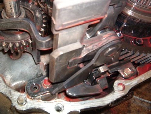
Now, remove the gear selector mechanism held in place by three 10mm bolts
8
Next step is to remove the 3 bolt bracket located beneath the gear stack attached to the input shaft.
9
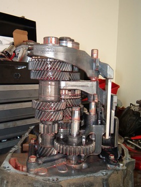
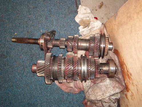
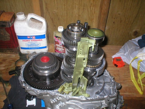
Once the three last bolts are removed, the gear stacks are ready to be removed simultaneously. Be careful with this because you dont want to damage any of the bearings and the rubber seal located on the bellhousing which seals the input shaft.
10
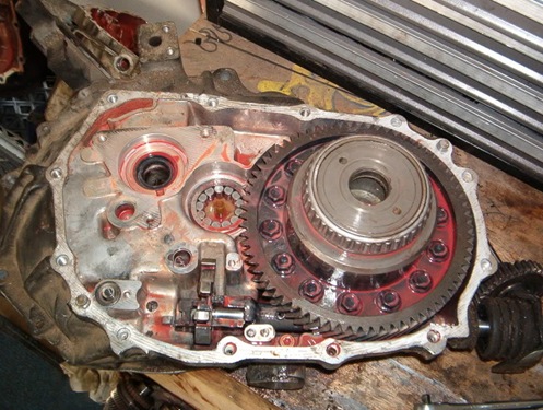
Now you will see this! The stock VLSD unit is just chillin there not attached to anything. Removing it is the easiest thing evar!!1!
11
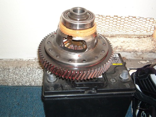
This is the working LSD unit out of the cracked donor transmission that will be swapped over to my transmission.
12
Reassembly is pretty much the exact opposite of the disassembly.


This is a good thing for those of you who have a crap load of spare trannies laying around with miscellaneous problems. You can essentially build a good transmission out other busted ones. Its nice to have it as a spare just incase.


I know this write up isnt all that great, but i hope it somewhat helps anyone who is going to attempt to repair their own transmission

tHe iLleSt RiCe@sr20

B14 Starter Removal


0 ความคิดเห็น


Removal of Starter for the B14.


Disconnect the battery when working on any electrical components. This is one of those cases.


Remove the intake or just have it loose to get to the 2 14mm bolts that hold the starter in place.


Position of starter bolts on the tranny housing
1
Jack the car up on jack stands


Little side note: The B13’s do not have the black V-plate.
Also, I DID NOT remove this plate, just got it loose so that there was room to take the starter out and put it back in.


Since you have the 2 long screws that hold the starter in place loose, you can remove the 2 connections to the starter. Connection (1) is a plug and the other is the connection (2) directly to the starter ..that one is a 12mm hex nut. (Connections 1 and 2)
2
The black V-plate is hard to miss but the bolts are a bit tricky to find. Locate bolts (1) and (2) with your fingers before you proceed to remove them. Bolt # 2 is easier to take out from the top so that could be done earlier in the process. It is located just below the IACV (idle air control valve)
(Bolt 1)
3
(Bolt 2)
4
The top bolts are actually hex nuts, 12 mm in size. Remove both of them. Then remove the remaining two bolts, (3) and (4) which are 14mm in size.
(Bolts 3 and 4)
5
Removing these bolts allows room to remove the starter. It’s a bit tricky so you have to find some angels that will allow the starter to come out.
New starter in place
6
Install the starter in reverse order that you took it out. When you have all of the connections made, plug the battery in and wait a sec to be sure that you did not connect anything wrong and that nothing is sparking that would cause a fire in your engine bay.
Turn that sucker over and jump for joy that you just saved yourself a few hundred dollars worth of labor!! YAY!!

strobe14@sr20

LSD axle vs. non-LSD axle comparison pics


0 ความคิดเห็น


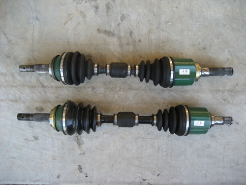
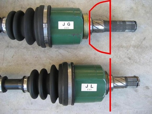
I had a non-LSD and LSD axle (both driver side) side by side yesterday and decided to snap some pics. The LSD axle is above and the non-LSD axle is below. On an LSD transmission the LSD itself is located on the driver side and bulges out several inches. The shape of the driver side LSD axle reflects that (the passenger side axle is the same regardless of LSD). This is why you can’t use LSD axles in a non-LSD transmission or vice versa. They are very similar, but quite different.

1

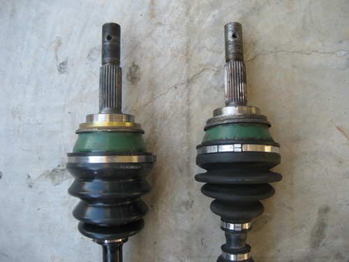
The hub ends are identical:

2

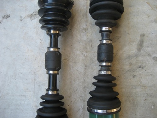
The center sections are similar, but elongated on the non-LSD axle:

3

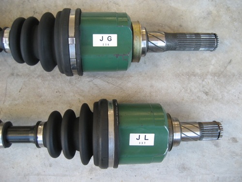
Here are the “business ends.” The LSD is labeled “J G” and the non-LSD is labeled “J L,” but I’m not sure if all OEM axles were labeled this way. The LSD axle has much longer splines, but notice both axles are actually the same length overall:


4

If you’re still having trouble seeing how this all works, here is a drawing that shows how the LSD bulge comes into play:

5

swiss@sr20

Sentra SE-R Coolant Change


0 ความคิดเห็น


You will have to change coolant at sometime in the life of your car, whether required by the periodic maintenance schedule, hose replacement, or a major component repair.The mighty SR20DE is a strong, sophisticated, aluminum power plant, so use care and common sense.

This procedure requires less than two hours can be performed alone. It was done on a 1992 Sentra SE-R, and likely applies to all North American versions of the SR20DE-powered Sentra and 200SX produced since the 1991 model year. If in doubt, check with your dealer and the factory service manual. Optimum results are allegedly achieved by strictly following the factory service manual, but the method here has given me excellent results.

Tools and supplies: anti-freeze; distilled water; ratchet; sockets in 10mm and 14mm sizes; extensions in various sizes; small and large Phillips screwdrivers; large drain pan; funnel; Loctite PST sealant

View the photos before beginning!

  • Allow the car to cool for few hours or overnight.
  • Move the car outside. Otherwise, be prepared to catch a lot of water in some large drain pans.
  • Move the heater control to full hot.
  • Remove the right front splash shield using a ratchet, 10mm socket, and Phillips screwdriver.
  • Place a large pan under the radiator drain plug and engine block drain plug.
  • Remove the radiator cap, then remove the rear bleeder cap and radiator drain plug using a Phillips screwdriver. Coolant will drain.
  • Remove the front bleeder plug using a ratchet, extension, and 10mm socket.
  • Remove the engine block plug using a ratchet, extension, and 14mm socket. More coolant will drain.
  • Move the drain pain out from beneath the car.
  • Flush the radiator for about 30 seconds by running water from a garden hose through the radiator filler.
  • Temporarily install the radiator drain plug and engine block drain plug until finger tight.
  • Flush the engine block for 30 seconds by running water from garden hose through the radiator filler, allowing water to spill from the front bleeder.
  • Temporarily install the front bleeder plug until finger tight.
  • Flush the heater plumbing for about 30 seconds minute by running water from garden hose through the radiator filler, allowing water to spill from the rear bleeder.
  • Once again remove the radiator drain plug, engine block drain plug, and front bleeder plug. Allow all fluid to drain.
  • Remove the coolant reservoir, drain it into the pan, and install.

If coolant has been drained to allow replacement or repair of a cooling system component, stop now. Perform the required work, then continue below.

  • Install the radiator drain plug.
  • Apply Loctite PST sealant to the engine block plug and install it.
  • With the front and rear bleeders still open and the heater control to full hot, fill the radiator and coolant reservoir with a mix of your favorite anti-freeze and distilled water (between 50/50 and 70/30 anti-freeze to distilled water is typical) until some spills from the front bleeder.
  • Install the front bleeder plug.
  • Fill the radiator with more coolant until some spills from the rear bleeder.
  • Install the rear bleeder cap and radiator cap.
  • Start the engine. Listen for strange noises, check for leaks, and keep an eye on the temperature gauge to avoid overheating.
  • After the radiator fan begins to run, allow the engine to run a few more minutes, then shut down.
  • Allow the engine to cool for an hour, then remove the rear bleeder cap and radiator cap.
  • Fill the coolant reservoir if necessary, and fill the radiator until fluid spills from the rear bleeder.
  • Install the rear bleeder cap and radiator cap. At this point, the cooling system should be sufficiently purged of air. With the engine running, you should feel hot air from the heater and hear no noises from the heater core. Note: the reservoir usually completes the last little bit of this job for you, so check the coolant level routinely after each drive over the next few days.
  • Close the hood, lower the car, and go for a drive! Watch the temperature gauge, listen for strange noises, and check for leaks upon return.

www.se-r.net

How to Upgrade your brakes (B13 NX2000)


0 ความคิดเห็น


B13 Sentra Brake Upgrade Install Instructions


1. Assemble the proper parts and tools. You'll need a new brake master cylinder from an NX2000 (unless you already drive an NX), new front rotors, new front calipers, pads and shims. Additionally, you'll need a set of metric open-end wrenches or a ratchet set, a 10mm flare nut wrench, a jigsaw, rotary (Dremel) tool or other tool suitable for cutting sheet metal, a brake bleeder hose, and a couple of pints of brake fluid. You may also want to have a long-handled pipe wrench or torque wrench handy, in case some of your bolts are on too tight for a standard wrench. If your car is a Sentra SE-R and you plan to use stock wheels, you need to grind 1.5 - 2 mm off the outside edge of the calipers in order for them to fit (a machine shop will be happy to do this for you, for a few dollars). After the calipers are ground, paint them with 500 degree paint to inhibit rust.


Master Cylinder


Place a thick layer of shop towels under the brake master cylinder. It's located just inboard of the left front shock tower. There are four metal tubes that run out of the MC; these are your brake lines. Using a10mm flare nut wrench, disconnect these tubes from the MC. The tubes are filled with brake fluid and some will leak out -- that's why the shop towels are there. The nuts that hold the tubes on are quite tight, so it'll take some muscle to get 'em off. You may find it convenient to remove your air intake box to get easier access to some of the tubes.


Once the brake lines are disconnected, you can remove the MC. Along the firewall, two bolts hold the MC to the brake booster. Unfasten these, holding the MC steady as you do the last few turns. Carefully remove the old MC from the car; you don't want to spill fluid if you can avoid it. (Note: if one is available, you can use a turkey baster to remove brake fluid from the reservoir atop the master cylinder. However, the author is not responsible for any domestic conflict that may result from this act).


Pour some new brake fluid into the reservoir of the new MC. Actuate the pistons by sticking a screwdriver into the hole in the MC and gently pressing harder. Pump the pistons until fluid starts to ooze out of all 4 holes on the MC. Now, reverse the removal process to install the new MC. Bolt the MC to the booster, then attach the brake lines. Your "heart transplant" is complete; you can now move on to the calipers.


Calipers/Rotors


Jack up the car at the front and remove both front wheels. Inspect all parts so you'll have a good understanding of what you're about to attempt. If you look into the wheel well, the rotor is the big thick metal disc that you're staring at, and the caliper is the black or grey metal piece that's clamped on to the rotor. The brake line joins the brake hose at the top of the wheel well, and the hose runs down to the back of the caliper, where it's fastened by a bolt. Actually, the caliper is really 2 pieces, the caliper frame or torque member which holds the pads, and the caliper proper, which contains the piston and which squeezes the pads when you step on the brake pedal.


First, loosen the bolt which fastens the hose to the back of the caliper. Don't take it off, just crack it a little bit so it's easier to turn. It's tough to get enough torque to take off that bolt once you've unbolted the caliper from the hub if you don't do this. Now, attach a piece of wire from the bolt you've just loosened to some convenient spot on the strut tower. This is to prevent the brake hose from stretching when you remove the caliper; if you don't do this, the caliper will hang by the hose after you unbolt it from the hub.


Now you're ready to unbolt the caliper from the hub. The caliper frame is fastened to the hub by two bolts; the heads of these bolts are behind the rotor. Unfasten them (this is where I needed a long-handled wrench). The caliper is now held in place only by the clamping power of the caliper itself, which is clamped onto the rotor. Wiggle the caliper assembly off the rotor and gently ease it into a position where it's hanging by the wire you've just fastened. Remove the rotor from the hub and set it aside; you don't need it anymore.


Grab one of the two new torque members from your new brakes (if it's attached to the caliper, just slide it off the slider bolts). Hold it up to the spot where you've just removed the old caliper and frame, where you'll be bolting it in. It won't fit! (That is, I know it won't, if your car is a Sentra. I have no knowledge of fit problems with the NX or the 200SX). The splash guard, a piece of sheet metal just behind where the rotor used to be, is in the way. Using the new torque member as a guide, cut away the sections of the splash guard that interfere with proper fit. Once this is done, slide a new rotor onto the hub and check to make sure that the splash guard doesn't contact the rotor. If it does, cut away any offending part of the splash guard. Some people advocate cutting off the entire splash guard, claiming that this will help cooling.


Now, assemble the caliper system. Slide the torque member onto the caliper, making sure that the slider bolts are well lubricated. Insert the new clips, shims and pads into your new caliper, using the old caliper as a guide for what goes where.


With the rotor on the hub, slide the caliper assembly onto the rotor and into place. Bolt it onto the hub. Now, remove the bolt that fastens the hose to the old caliper, which has been hanging by a wire all this time. Make sure you save both copper washers. Fasten this bolt, with washers as they were on the old caliper, onto the new caliper. You can now remove the old caliper and the suspending wire.


Obviously, you need to repeat this process for the other front wheel.


Bleeding the system


It's possible that during the installation of the master cylinder or the calipers, pockets of air have entered your brake lines. These will inhibit proper brake function and must be removed by bleeding the brake lines. Standard bleeding procedure requires two people, though three is preferable. Bleed the brakes in order:


1. Left rear
2. Right front
3. Left front
4. Right rear


Bleeding procedure: Jack up the car at the proper corner and remove the relevant wheel. Fasten a clear plastic bleeder hose to the bleeder valve on the caliper, and place the other end of the hose inside an empty soda bottle or other container. This tool is available for around $6 at any auto parts store. Open the bleeder valve with a 10mm wrench. One individual climbs (gently!) into the driver's seat and pumps the brakes. Another watches brake fluid coming out of the caliper through the bleeder hose. A third watches the fluid level in the reservoir atop the master cylinder, pouring new fluid into the MC as necessary. When new fluid is coming out of the hose with no air bubbles, close the bleeder valve. Repeat this procedure for each wheel. When you're done, the brake pedal should be rock hard. If it's "spongy", you've still got air in the system somewhere -- bleed it again until it's all out.


Source: Jim Wright/Don Dale
Friday, October 16, 2009

Cleaning the AAC Valve


0 ความคิดเห็น


Ive been attempting to locate my strange hesitation issue. I searched around and there was a possibilty of the aac valve being dirty & or clogged. I removed it and cleaned it out. The car does drive smoother but didnt cure my hesitation. Heres the pics and general info for you feast your eyes on.


Heres the location of the AAC Valve itself (just left of the oil filter). Its held on with 4 bolts.

1

I dont have a/c in my car so removing and installing the valve was not a major issue at all. Takes about 5 min tops with no a/c lines in your way. With the a/c lines in it will be a PITA. 10mm for all 4 bolts.

2

Heres the valve removed.

3

Heres the area to clean, mine didnt look to bad.. You wanto make sure and remove the sensor from the body (2 screws) before cleaning it out. I used carb cleaner and Q-tips.

4

And here she is all minty fresh.

5

I added a very thin coat of gasket maker to it before installing again. You will find the top 2 and bottom left bolts area very easy to put back in. The bottom right bolt is in a funny spot and will require you use both hands to screw it in. I attempted with one hand and the bolt fell. It didnt hit the ground and I couldnt locate it until I backed out my driveway and heard it fall out. If I missed anything please chime in. -Adam

B15/P11 tranny- why it's better than B13/B14


0 ความคิดเห็น


Well, I started pulling my B15 tranny apart today to install my friction type LSD and thought I'd share with all of you a little bit of what I found. We all know that B15 trannys hold up to high HP way better than B13/B14 trannys and I've frequently seen many folks wondering what exactly is responsible for this. Unfortunately, there really hasn't been any definitive answer. Thanks to a friend of mine who has many torn apart B13 trannys, I was able to compare and spot some big changes in the B15 tranny. Hopefully what I have found will shed some light on the major differences. I am assuming that the P11 tranny is identical but I don't have one to compare with here.


What we already know:
There is some seperation of the input and main shafts under WOT that occurs in B13/B14 trannys. This puts a great deal of stress on the ends of the gear teeth (at its worst in 3rd) leading to shearing in high HP scenarios. The B15 tranny does not seem to have this problem and thus holds up much better to high HP applications.


But why?:
Obviously the B15 case is significantly different than B13/B14 cases. An addition that was made with the introduction of the B15 tranny is pictured below.

11

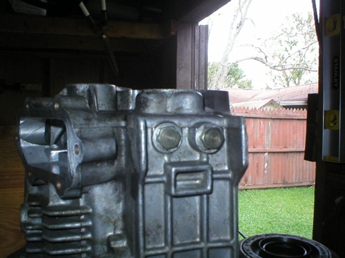
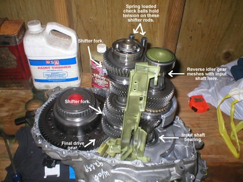
The two seemingly pointless 14mm bolts pictured actually serve a very important purpose and that is reinforcement. Inside the sleeves that they screw into is a small spring that holds pressure on a check ball (2 springs and 2 check balls total). The check balls contact the two shifter rods that 'ride' the main shaft and essentially hold tension on them when in place. The shifter rods are notched where the check balls contact them and you cannot even remove the case without removing those two bolts first. This is quite a nice improvement over the B13/B14 design where the shifter rods are loose at best. In addition to this, the shifter rod that 'rides' the input shaft sports a much beefier fork and sits with much more stability over the B13/B14 counterpart. Support, stability and reinforcement are obviously greatly improved.


As far as the internals go, everything is different, including the diff. IMHO, it seems like the gear stacks are beefier on the B15 tranny (see pic below). Sorry that I have no comparison pics with a B13 or B14 tranny.

13

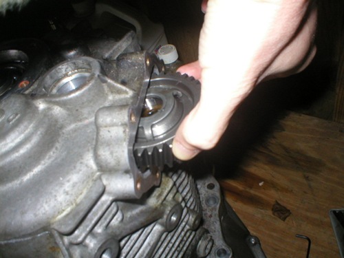
Probably the biggest difference that sets the B15 tranny apart though is the positioning of the reverse idler gear. To get to the gear, you must take off the small cover pictured below, and remove its retainer pin (also pictured below). This gear is actually held into the tranny case itself (by the retainer pin) and meshes with the input shaft. It basically forces the input shaft to stay completely meshed with the main shaft, yet another reason why there is virtually no play in these trannys.

3 

Reverse idler gear cover

4

Removing the snap ring to take out the retainer pin.

5

Threading a small bolt from the cover into the retainer pin to lift it out.

6

The actual retainer pin removed.

7

After the pin is removed, the reverse idler gear pulls right out of the case.


So to highlight how the input and main shafts stay meshed in the B15 tranny, I give you the following synopsis:


Input shaft: Supported on one end by the input shaft bearing and on the other end by the reverse idler gear and a better design rear bearing, thereby preventing play under WOT.


Main shaft: Supported on one end by the diff final drive gear and on the other by the spring-loaded check balls as well as the bearing race, thereby preventing play under WOT.

13_2

Hope this sheds some light on some big differences between the two types of trannys...

coalitionSE-L@sr20

Nissan Planning Next-Gen R36 GT-R for 2013


0 ความคิดเห็น


SpecV-Drive-053

Nissan’s product planning head has made known plans to keep the GT-R legacy alive with an all-new R36 version of the car expected to debut by at least 2013.

Global product boss Andy Palmer made the comments to the folks at PistonHeads, during a recent visit to Nissan’s Nürburgring Technical Center this week. Palmer cited the hard economic times as the reason to cut certain projects within the company, but cited the importance of the GT-R as a performance halo car. The GT-R helps brand Nissan as a performance car company, much in the same way the upcoming Leaf electric car will help give the Japanese automaker a green appeal.

Palmer didn’t say much about the R36 GT-R other than the fact that we should expect the twin-turbo V6 powerplant to stay in place, as well as the all-wheel drive setup.

Nissan is committed to its flagship sports car and aims to stick to a production schedule that will see them compete with Porsche.

SpecV-Drive-081

Source : PistonHeads

How to Make an o2 sensor wire extension.


0 ความคิดเห็น


Well seeing as the stock o2 sensor wire is to short to reach the bung on the DET t25/t28 J-pipe I decided to make an extension that I could just plug in with out cutting or soldering. The best way to do this is to Crimp all the connections. AFAIK Soldering the connections is not the best idea because over time it will deteriorate from the elements and eventually crack and fail.


I put mine together using some connectors from a wiring harness I had lying around in my basement. If you go to the dealership you might be able to have them order a male and female connector but I’m not sure about that. I suppose you could also sweet talk a Junk yard guy into letting you snip a few connectors but I don’t see that happening.

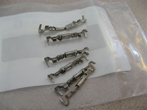
So I do know for sure you can get the proper pins from the dealer for pretty cheap. This is where I got mine. I paid a whopping $0.08 for all of them (you need to make sure you get the ones that have the ring to hold the insulator on the end of them):

IMG_2111

Now my dealer didn’t have the correct size insulators. You want to use the black ones because they are for 18-16 gage wire. I salvaged some good one from my wiring harness so I didn’t need to order any from them.


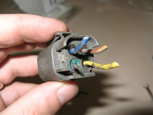
I cut a plug off my extra harness:

IMG_2107

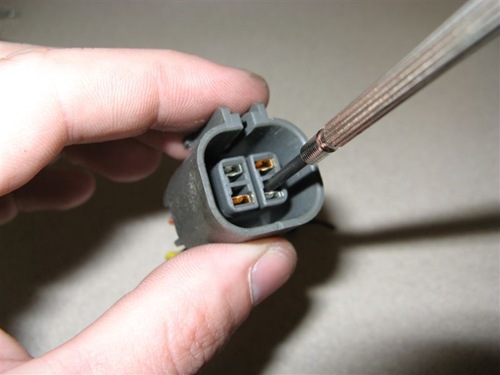
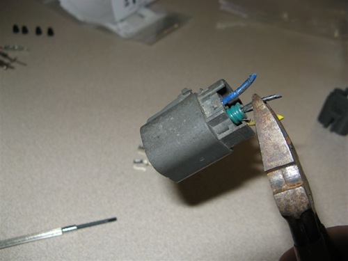
Pop the pins out with a small flathead screw driver:

IMG_2108

And remove the pins with the insulators connected to them:

IMG_2110

Removing the insulators from the pins was fairly easy. Just remember you want to reuse the rubber insulator part so be gentle with it.

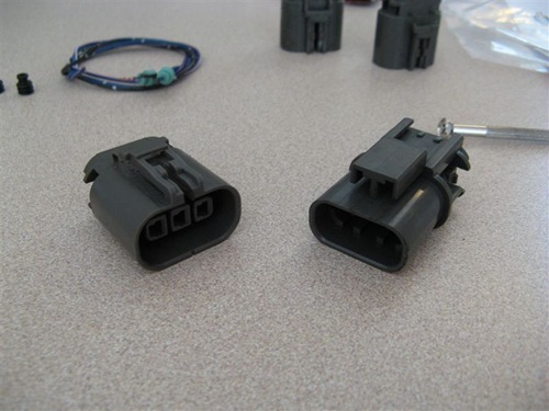
This is my donor connector. (I had to cut the male end off a junk o2 sensor because my wiring harness only had the female connectors on them). I removed the pins from them and disassembled the connectors the same way as described above:

IMG_21141

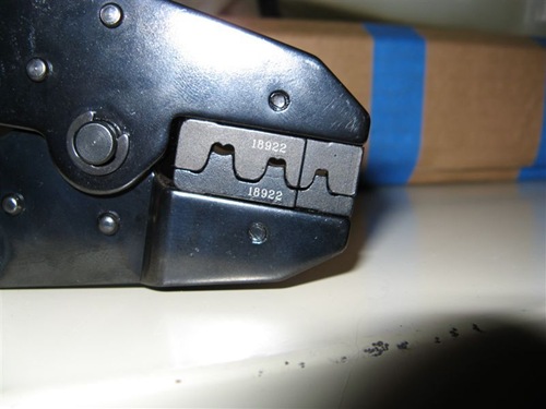
Now for the crimping needs you need to use a special terminal crimper. It’s specially designed to crimp Weatherpack terminals. I found this one on Ebay for approximately $30 shipped:

IMG_22241

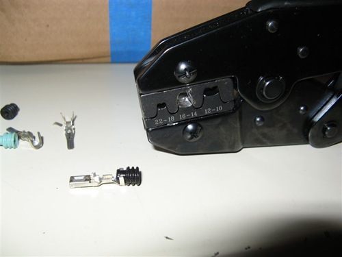
Although it was designed to crimp the Weatherpack "like" terminals I needed to modify it so I could use it to crimp the terminals designed with the insulator rings on them. It was pretty easy to do with the Dremel and a carbide bit. This is how the opposite side looked when I was finished (I decided to use the 16gage die crimp for these terminals.):

IMG_2220

If you look around hard enough you can find the proper crimper for the job. They are designed to crimp terminals with the insulators on them but all the ones I found were $100 or more plus shipping. I’m cheap so modifying the one I got was the easier way to go.


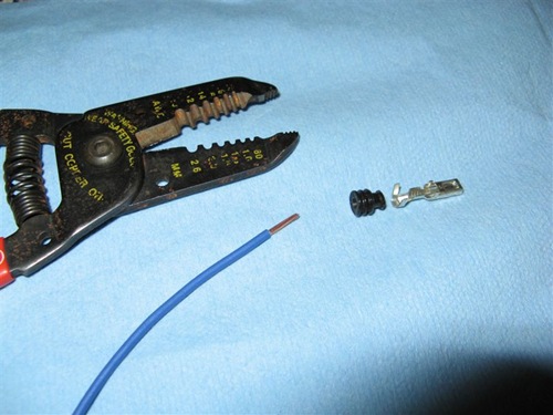
So on to the crimping. First you need to get some wire. 18-14 gage should be fine. I’d stay on the smaller side because the factor wiring size looks like it’s about 18gage or so.


Now strip off about .25” of the wire insulation.

IMG_2231

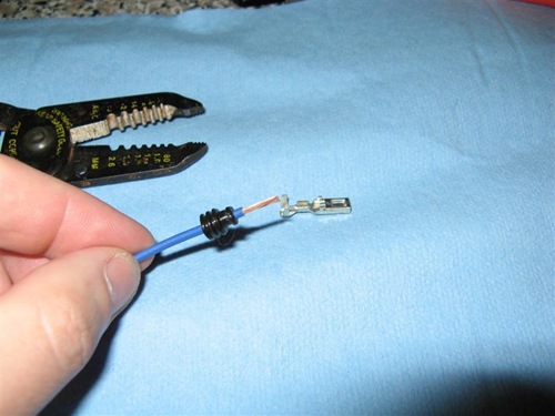
Slide one the insulator:

IMG_2232

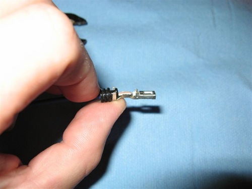
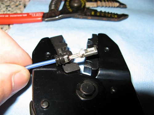
Assemble it so it’s ready to crimp:

IMG_2233

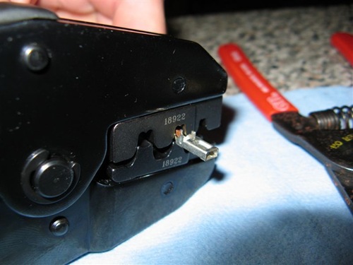
And crimp it up!

IMG_2234

This is how it should look after it crimped. Almost factory quality:

IMG_2235

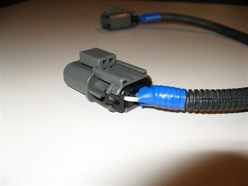
Now all you need to do is crimp up the rest of the wires, pop them back into the connectors, snap the black terminal keeper back on and cover the wire however you like.


I used some of the black wire sheath you can get from the auto store and I taped the ends up like they do with the factory wiring harness.

IMG_2250

I made it about @ 14” long. I may redo it and make it longer but I won’t know for sure if I have to until I drop everything in.

Mike@sr20


© Copyright 2009 by SR20 Party